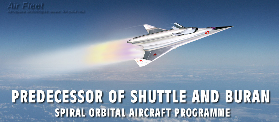
The Spiral seems to be one of the most ambitious and secret projects in the history of Soviet aviation. Therefore, only 40 years later it became possible to disclose the whole truth of this aircraft...
Under the five-year plan of the Air Force on orbital and hypersonic aircraft,
go-ahead to actually proceed with development of a manned orbital vehicle in the
USSR was given in 1965 to the Artem Mikoyan's OKB-155 design bureau, and
55-year-old Chief Designer Gleb Lozino-Lozinsky was selected as project manager.
The new project dubbed Spiral.
The aerospaceplane project dated 29 June 1966 provided for the development of a
115-t orbital system consisting of three winged VTOL reusable aircraft: the 52-t
HLA reusable hypersonic air-breathing launch aircraft, designated '50-50'; the
RB expendable two stage rocket booster; and the OS manned orbital aerospaceplane,
designated '50'. The system would take off vertically from a launch cart at a
takeoff speed of 380-400 km/h.
 The launch aircraft would accelerate the whole system to a hypersonic speed of M=6
(about 1,800 metres per second), releasing the components at an altitude of
28-30 km. The launch aircraft would return to its launch base after completing
the mission, and the booster, burning fluorine+hydrogen fuel, would propel the
aerospaceplane to the orbit.
The launch aircraft would accelerate the whole system to a hypersonic speed of M=6
(about 1,800 metres per second), releasing the components at an altitude of
28-30 km. The launch aircraft would return to its launch base after completing
the mission, and the booster, burning fluorine+hydrogen fuel, would propel the
aerospaceplane to the orbit.
The orbital aircraft would bring a payload of up to 10.3 tonnes to the
circumpolar orbit of 130-150 km at the carrier offset of up to 750 km, if
boosted by a launch aircraft with liquid hydrogen power plant, or 5 tonnes if
the launch aircraft burnt kerosene.
The manned reusable single-seated orbital aircraft would be employed in daytime
photographic reconnaissance, radar reconnaissance, space targets interception or
ground attack, equipped with a space-surface missile for the latter function.
The aircraft weighed 8.8 tonnes in all configurations, carrying 500 kg of combat
payload for reconnaissance and interception, and 2,000 kg in attack
configuration. Launched from the territory of the USSR, the aircraft would reach
the 130-150-km orbits, inclined by 45-135 degrees. Manoeuvrability
characteristics of the aircraft, propelled by the rocket booster power plant,
burning fluorine and amidol provided for variable orbit inclination (to allow
second target run) by 17 degrees for the reconnaissance and interception
aircraft, and 7-8 degrees for an attack aerospaceplane armed with a missile. The
interceptor version would perform a combined manoeuvre of simultaneously
changing the inclination and ascending to 1,000 km, after which it would lose
the weight to 4,900 kg.
To complete the flight, the pilot would start braking engines and the orbital
aircraft would dive into the atmosphere at a large angle of attack, its roll
deflecting from 0 to 60 deg. at stable angle of attack to control the aircraft
on descent. It would be able of performing an aerodynamic manoeuvre at gliding
trajectory within the range of 4,000-6,000 km and side deviation of 1,500 km.
The aircraft would be guided to the landing area controlling the speed vector
along the runway, which was achieved through the use of the roll programme. The
agility of the aircraft would allow it to land at a speed of less than 250 km/h
at night and in adverse weather at one of reserve 2nd class airfields in the
USSR from any of its three orbit circuits, for which the RD36-35 kerosene-fuel
turbojet engine of the Rybinsk-based OKB-36 design bureau (Chief Designer Pyotr
Kolesov) would be used.
|
HLA DIMENSIONS |
|
| Fuselage length, m | 38.0 |
| Wingspan, m | 16.5 |
| Wing area, sq.m | 240.0 |
| Wing section, at board/at tips | 0.025/0.03 |
| Elevon area, sq.m | 24.0 |
| Wing aspect ratio | 1.14 |
| Forward edge sweep angle, degrees | 80/60 |
| Fuselage diameter (max), m | 4.15 |
| Middle section | |
| (incl. wing and engine nacelles), sq.m | 20.9 |
| Fuselage width (in engine nacelles), m | 6.2 |
| Winglet area, sq.m | 2x18.5 |
| Ventral fin area, sq.m | 10.0 |
The hypersonic launch aircraft had a layout of a large arrow-shaped variable
flying wing, with vertical stabilisers mounted at the wingtips. The wing is made
of double-wedge profile section featuring variable thickness ratio.
HLA control surfaces included rudders of the fins, elevons and landing flaps. To
improve its yaw stability, the tail unit incorporated a ventral fin, folding at
take-off. The aircraft featured a two ejection seat insulated cockpit, its nose
declining 5 degrees forward at landing to allow better field of view.
Liquid hydrogen was used as propellant for the launch aircraft. The power plant
included a set of four AL-51 turbojet engines boasting 17.5 tonnes of thrust
each designed by Arkhip Lyulka's OKB-165. They had a single air intake and a
single supersonic divergent nozzle.
With the empty weight of 36,000 kg, the launch aircraft could carry up to 16,000
kg of liquid hydrogen in tanks of 260 m3 each.
The engines' peculiarity consisted in the use of hydrogen vapours to gear the
turbine that rotated the turbojet compressor. Hydrogen evaporator was placed at
the compressor inlet. This is the way the powerplant for the aircraft was
elaborated without combining turbofan, hypersonic and turbojet engines.
The adjustable hypersonic air intake was yet another advanced feature of the
launch aircraft. It used almost entirely the forward bottom surface of the wing
and the specially designed fuselage nose to compress the air.
Dedicated construction materials and heat-resistant coatings were applied to
withstand the heat barrier.
The launch aircraft might well have been used as a long-range hypersonic
strategic reconnaissance aircraft, too. Equipped with kerosene engines, it was
expected to accelerate to M=4.0-4.5 and have a range of 6,000-7,000 km at
cruising M=4, while the hydrogen engine installed would allow it to speed up to
M=6 and cruise 12,000 km at M=5.
The OS was implanted into the launch aircraft on top, together with the rocket
booster in the shape of two-stage launch vehicle with the total length of 27.75
m (18.0 m for the first stage and the fairing and the remaining 9.75 m for the
second stage with the orbital aerospaceplane proper). The oxygen-hydrogen
booster would be a meter longer and a half-meter thicker.
The aerospaceplane itself was a flat-bottomed lifting body with a large upturned
nose. The nosecone was made as a 60-deg. segment with 1.5-m radius of the sphere.
Its design was found to greatly reduce afterbody heating during re-entry, when
it heated to 1,400 deg. Centigrade.
| COMPARATIVE PERFORMANCE OF ROCKET BOOSTERS | ||
| Versions | main | intermediate |
| Specific pulse, s | 460 | 455 |
| Length with orbital spacecraft (OS) and fairing, m | 27.75 | 28.71 |
| Empty weight, t | 6.15 | 8.62 |
| Takeoff weight (without OS), t | 52.7 | 51.12 |
| Mixture ratio | 1:14 | 1:7.5 |
| 1st stage: | ||
| empty weight, t | 5.5 | 7.7 |
| fuel | liquid Н2 | liquid Н2 |
| weight, t | 2.8 | 4,5 |
| volume, cu.m | 40.0 | 60.0 |
| oxidiser | liquid F2 | liquid O2 |
| weight, t | 39.2 | 33.75 |
| volume, cu.m | 25 | 30.9 |
| tank diameter, m | 2.5 | 3.0 |
| Takeoff weight, t | 47.5 | 45.95 |
| 2nd stage: | ||
| empty weight, kg | 650 | 920 |
| fuel | liquid Н2 | liquid Н2 |
| weight, kg | 310 | 500 |
| volume, cu.m | 4.42 | 6.67 |
| oxidiser | liquid F2 | liquid O2 |
| weight, kg | 4.240 | 3.750 |
| volume, cu.m | 2.70 | 3.43 |
| tank diameter, m | 2.5 | 3.0 |
| Takeoff weight (without OS), kg | 5,200 | 5,170 |
A unique feature of the aerospaceplane was the variable dihedral wings. The
outer skin was articulated to permit thermal expansion during re-entry. The
wings were set at an angle and had a specific form, so that during re-entry at a
45-60 deg. angle of attack and the hypersonic quality of 0.8 the air stream
would flow from the body down to the wings, rather than to the wing leading
edges. Also, the wings were made separately variable to better controllability
in case of yawing.
 To improve landing parameters, after becoming subsonic, dual electric actuators
moved the wings to a horizontal position, where they served as wings,
substantially increasing the lift of the aerospaceplane for airbreathing
operations, the wingspan reaching 7.4 m with a sweep of 30 deg. This increased
the aerodynamic quality to 4.5.
To improve landing parameters, after becoming subsonic, dual electric actuators
moved the wings to a horizontal position, where they served as wings,
substantially increasing the lift of the aerospaceplane for airbreathing
operations, the wingspan reaching 7.4 m with a sweep of 30 deg. This increased
the aerodynamic quality to 4.5.
The 'hot structure' principle was used in ensuring heat resistant capability of
the orbital aerospaceplane. Therefore, the aircraft had a welded frame, with a
heat-resistant screen underneath, made of plates of the VN5AP clad columbium
alloy coated with molybdenum dicilicide. The plates were placed as fish scales.
The screen was attached with the help of ceramic bearings playing the part of
heat barriers, as they relieved temperature stress by means of the screen moving
relative to the body without changing the shape of the aircraft.
Landing gear normally consisted of four skids in landing gear bays mounted on
the sides of the aerospaceplane above the heat shield, and deploying in the
manner not to split the screen before landing.
|
ORBITAL AEROSPACEPLANE DIMENSIONS |
|
| Body length, m | 8.0 |
| Body rear edge span, m | 4.0 |
| Body front section radius, m | 1.5 |
| Planform area, sq.m | 24.0 |
| Body middle section, sq.m | 3.7 |
| Body bottom area, sq.m | 2.8 |
| Nose sweepback angle, deg. | 74.33 |
| Variable wing area, sq.m | 2x33.0 |
| Wing leading edge sweepback angle, deg. | 55 |
| Elevon area, sq.m | 1.84 |
| Fin area, sq.m | 1.7 |
| Rudder area, sq.m | 0.44 |
| Flap area, sq.m | 1.785 |
The power plant included:
- a liquid propellant engine (LPE) for orbital propulsion, with the 1,500 kg/f
of thrust (specific pulse of 320 sec, fuel consumption of 4.7 kg/sec). It was
employed to change orbital inclination and produce a braking pulse to dive off
the orbit. Later versions would feature a more powerful LPE with thrust in
vacuum of 5,000 kg/f, boasting a variable thrust capability, adjusting it
slightly to 1,500 kg/f to allow orbital manoeuvres;
- two emergency situation braking 16 kg/f LPEs, fed from main LPE fuel system by
the compressed helium displacer;
- an LPE attitude control unit of six 16 kg/f engines for coarse adjustment and
ten 1 kg/f engines for fine manoeuvres;
- a turbojet kerosene 2,000 kg/f engine with specific fuel consumption of 1.38
kg/kg*h to allow subsonic propulsion and landing. It had an adjustable ram air
intake at the bottom of the fin, opened only before starting the turbojet.
The first examples of combat orbital aerospaceplanes were to be equipped with
intermediate LPEs, burning fluorine-ammonia fuel.
The pilot-cosmonaut sat in an insulated 'headlight' escape capsule, equipped
with powder charges to eject the capsule at any stage of flight from taking-off
to landing. The capsule also had control engines for re-entry phase, as well as
a radio beacon, an accumulator and an emergency navigation unit. It parachuted
at a speed of 8 m/s, kinetic energy absorption effected by means of residual
deformation of the specially designed cellular structure of the capsule bottom.
The escape capsule with equipment, life-support system, escape system and the
pilot-cosmonaut weighed 930 kg, and 705 kg at landing.
The navigation and automatic control system included a self-sustained
astro-inertial navigation system, a digital airborne computer, LPE directional
equipment, astro-corrector, optical viewing device and radio altimeter.
Manual backup on direction signals was available to control the aerospaceplane
at descent.
Specialised equipment of the combat manned orbital aerospaceplanes in
reconnaissance and interceptor configurations was placed behind the cockpit in a
2 cu.m compartment, which was increased at the expense of the fuel compartment
to allow housing the space-surface missile in the ground-attack configuration.
Daytime photographic reconnaissance
aerospaceplane would provide detailed
intelligence on small-size land and mobile sea-surface targets, selected in
advance.
The photographic equipment ensured 1.2-m resolution, if employed from 130 km
orbit. The pilot-cosmonaut was to detect the target and observe the terrain with
the help of the optical viewing device. The device had an adjustable reflector
to track targets from 300 km. Picture-taking would start automatically as soon
as the pilot manually coincided the optical line of sight of the photo camera
and the viewing system with the target. The pilot should have time to make
photos of 3-4 targets during one circuit.
The reconnaissance aerospaceplane would have short-wave (HF) and ultra
short-wave (UHF) radios to transmit the data to ground control centre. If
additional target run required, an automatic orbit inclination changeover was
performed at pilot's command.
The
reconnaissance version would have a distinguishing 12x1.5-m external
expendable antenna, which was expected to be effective at 20-30 m, which is
quite enough to detect aircraft carrier groups and large land installations.
The
attack orbital aerospaceplane would be used to kill sea targets. It was
expected to launch its space-surface missile over the horizon with target
designation data available from an orbital reconnaissance aerospaceplane or a
satellite. Precise coordinates of the target would be specified by the locator,
expendable after the aerospaceplane changes the orbit, as well as by its
navigation equipment. Radio guidance at initial stage of combat trajectory would
allow increased precision of guidance to the target. With the launch weight of
1,700 kg, the missile would have a hit probability of 0.9 against aircraft
carriers cruising at a speed of up to 32 knots, if target designation accuracy
of 90 km is achieved.
The latest modification of the
combat orbital aerospaceplane was the
interceptor.
It had two versions.
The inspector-interceptor would obtain the orbit of the target, approach it to
3-5 km and even the speed. After that the pilot could either inspect the target
with the help of 50-fold magnification optical sight with a resolution of
1.5-2.5 m and take a picture of it, or attack it with the six 25-kg homing
missiles, developed by SKB MOP design bureau, which could kill targets within
the range of 30 km.
The interceptor would have fuel enough to intercept two
targets at 1000 km of altitude with the noncoplanarity of targets' orbits of up
to 10 degrees.
The long-range interceptor would have the SKB MOP's homing missiles, featuring
an optical coordinator to allow space target interception on collision course,
the interceptor's missing the target by 40 km to be compensated by the missile
proper. With its maximum range of 350 km, the missile weighed 170 kg in launch
container. The pilot would search and detect the target assigned in advance with
the help of the optical viewing system. The aircraft's fuel load provided for
the interception of two targets at altitudes of up to 1,000 km.
| COMPARATIVE SPECIFICATIONS OF TWO SPIRAL ORBITAL AEROSPACEPLANE VERSIONS | ||
| Versions | Baseline | Intermediate |
| HLA fuel | liquid Н2 | kerosene |
| RB fuel |
liquid F2 + liquid Н2 |
liquid О2 + liquid Н2 |
| Aerospaceplane fuel | F2+NH3 | AT fuel + dimethylhydrazone |
| Takeoff weight, kg | 115,000 | 129,920 |
| HLA characteristics: | ||
| takeoff weight, kg | 52,000 | 72,000 |
| empty weight, kg | 36,000 | 38,400 |
| RB 1st stage characteristics: | ||
| takeoff weight, kg | 47,500 | 45,950 |
| empty weight, kg | 5,500 | 7,700 |
| RB 2nd stage characteristics: | ||
| takeoff weight | ||
| (including aerospaceplane), kg | 15,500 | 11,970 |
| empty weight, kg | 650 | 920 |
| Aerospaceplane characteristics: | ||
| takeoff weight, kg | 8,800-10,300 | 6,800 |
| empty weight, kg | 4,190 | 4,190 |
| payload, kg | 500-2,000 | - |
| Release characteristics of aerospaceplane and HLA: | ||
| flight speed, m/sec | 1,800 | 1,200 |
| Mach number | 6 | 4 |
| altitude, km | 28-30 | 22-24 |
| Speed of 1st and 2nd RB stages' spilt, m/s | 4,500 | 4,280 |
| Base line orbit, km | 130-150 | 130-150 |
Given the complexity of the whole Spiral programme, the system was to be
developed stage-by-stage.
Stage One. There were plans to create a sub-orbital manned aircraft prototype (index
'50-11'), weighing about 11.85 tonnes, including fuel load of 7.45 tonnes, to be
propelled by two Leningrad-based OKB-117 11.75-tf rocket engines (Chief Designer
Sergey Izotov). The aircraft would be launched from the Tu-95KM launch aircraft
for the developers to assess its aerodynamics and test operation of manoeuvre
engines and fuel system. Three such aircraft were planned to undergo tests at
subsonic speed and at landing in 1967, supersonic and hypersonic flights
scheduled for 1968. These tests were intended to be a USSR response to the US
X-15 aerospaceplane programme.
Stage Two. It was planned to develop a 6.8-t single-seated Experimental Piloted
Orbital Aerospaceplane (Russian acronym - EPOS) to work through the full-scale
structure and carry out fly tests of avionics, EPOS's appearance being exactly
the same as that of the combat orbital aerospaceplane. EPOS would be carried to
the orbit of 150-160 km with the help of the Soyuz launch vehicle to make two or
three circuits, manoeuvring to change orbit inclination by 8 deg., after which
it would descend and land. Four unmanned and manned flights were scheduled for
1969 and 1970 respectively.
Stage Three. To speed up the development of the hypersonic launch aircraft, a
full-scale launch aircraft with R39-300 kerosene engines designed by
Moscow-based OKB-300 (Designer General Sergey Tumansky) was to undergo tests
first, the four prototypes to stand trials in 1970, reaching Mach 4. As soon as
there was enough data on aircraft aerodynamics and operation at hypersonic speed,
it would incorporate hydrogen engines, for which another four aircraft were to
be developed and tested.
Flight tests of the hydrogen version were scheduled for 1972, and the three
stages' cost was estimated at RR453 million.
Stage Four provided for tests of the fully equipped system, comprising a
kerosene HLA and an OS with RB, burning the mixture of liquid oxygen and
hydrogen. These were to be held 1972. After the trials, flight tests of the
hydrogen HLA were scheduled for 1973, carrying the manned OS.
Further steps would include use of liquid fluorine as an oxidiser for the RB and
OS, plus development of a reusable RB with supersonic ramjet engines.
The draft project development started in 1967, and prototypes were soon to be
assembled, but Designer General Artyom Mikoyan, backing the programme with his
authority, died on 9 December 1970.
After looking through the programme documentation early in 1971, Soviet Defence
Minister A. Grechko put forward a resolution: "We are not going to take up
fantasies!" He was backed by Dmitry Ustinov, Secretary of the Communist Party's
Central Committee, supervising defence industry. So, the Spiral programme was
aborted to transform into a set of research and development work, and the
technological solutions and flight tests of prototypes had no real grounds to
expect being implemented.
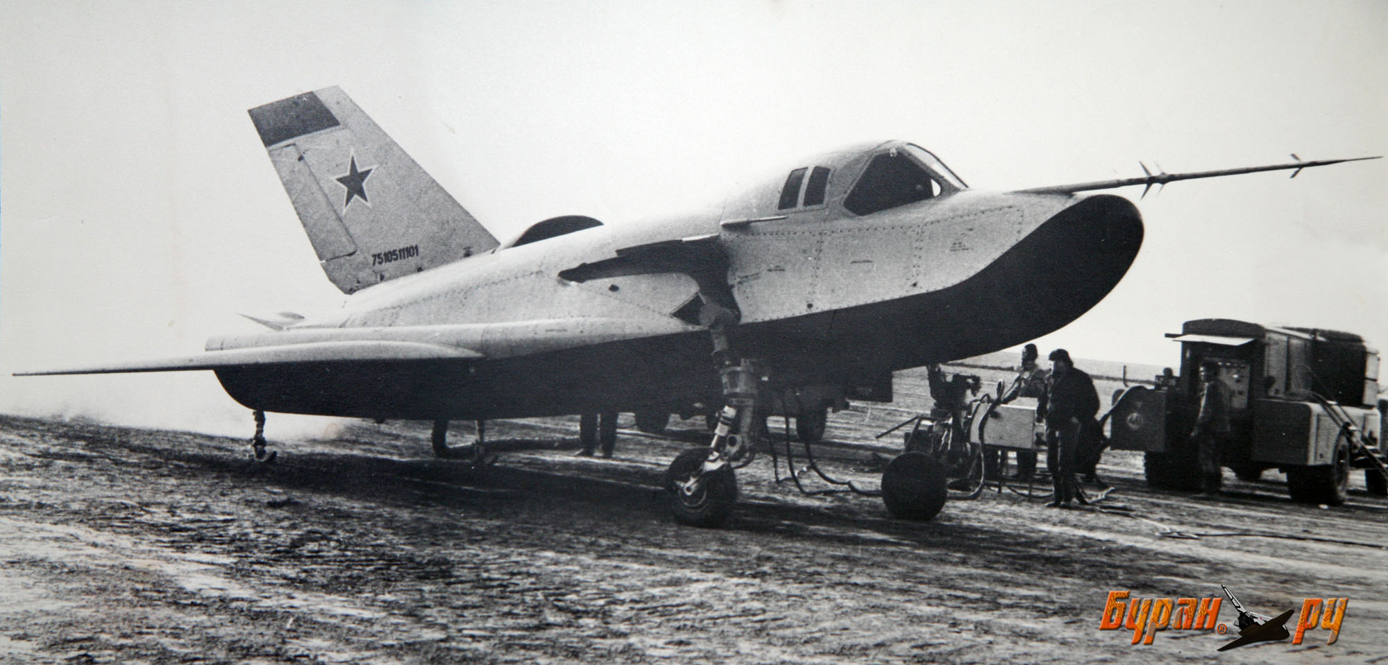
Before the programme was terminated entirely, three prototypes were built to
test stability and controllability at different flight stages:
- the first was used to test flight parameters at subsonic speed (simulating the
atmospheric stage of approaching for landing after leaving the orbit), code
named EPOS with the index of '105.11';
- the second one for supersonic tests (index '105.12');
- and a hypersonic prototype (index '105.13').
The first one had fixed wings for landing simulation. Its control surfaces were
purely those of common aircraft, including flaps, fin-mounted rudder and a trim
panel. It was propelled by the Kolesov RD36-35K turbojet, with the air intake on
top of the fuselage before the fin, as any other location would distort the
lifting body. The aircraft had a four-stick retractable landing gear with
plate-type skids.
Tests of this version were held at the proving ground of the NII VVS Air Force's
Research and Development institute in Akhtubinsk in the Astrakhan Region. Their
first stage included runs at continually increased speed with short-time
take-offs. A curious thing happened right at the beginning of the tests, after
which the forward landing gear skids were replaced with pneumatic wheels:
several trucks with watermelons had to be thrown onto the runway for the
aircraft to start moving.
Another problem surfaced with the absence of steering mechanism of the forward
landing gear, as rubber wheels used to lead the aircraft away from the central
runway line 150-180 m. A new set of tests were held but the problem was resolved.
 |
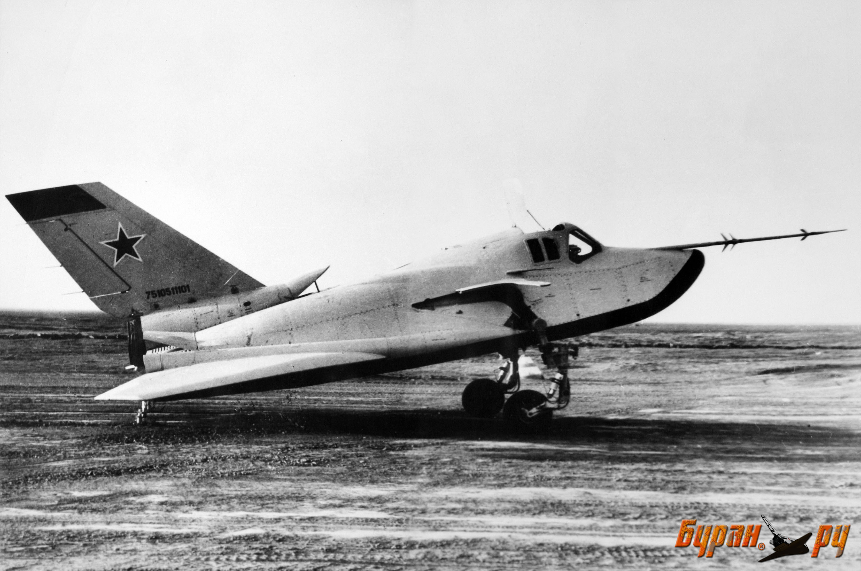 |
Due to all these, the flight tests commenced only in May 1976. The runway was
long enough for the aircraft to take-off and fly for 10-15 seconds, after which
it landed on the same runway. These tests were performed by test pilots Igor
Volk, Valery Menitsky and Aleksandr Fedotov, who proved the aircraft
specifications to be satisfactory. The greater part of tests, however, was
vested into Aviard Fastovets, who made a short 'flight-over' from one unpaved
runway to another on 11 October 1976.
The next stage of the tests came a year later. Under the programme, EPOS was to
be launched from under the fuselage of the Tu-95K aircraft, which was adjusted
for the mission, its bomb bay doors taken away and a suspension and lifting
system attached. EPOS having larger wingspan than the bomb bay hatch, it was
implanted into the carrier aircraft half-full, almost to the wings, its cockpit
coming inside the bomb bay to leave the pilot only a small view in the forward
looking hemisphere. Moreover, the air intake turned out to be inside the bomb
bay of the carrier aircraft, which required an auxiliary air charging system to
be mounted.
During the first several flights EPOS was not released from the carrier aircraft,
as a possibility of releasing it into the air stream on elongated racks and
igniting its engines in the launch position was tested. As soon as everything
was tested, the crucial phase of the tests started, with the EPOS air-dropped
for self-sustained flying and landing. On 27 October 1977, the Tu-95KM piloted by
Lieutenant-Colonel Aleksandr Obelov released the EPOS with Aviard Fastovets
behind the stick at 5,000 m into the landing glideslope of the airfield.
EPOS had nine more flights, during which its aerodynamics, stability,
controllability and the effectiveness of control surfaces were tested. One of
the flights after airdrop launch was performed by Pyotr Ostapenko.
After Grechko died, Dmitry Ustinov became the USSR Defence Minister in April
1976, his standing point on the development of combat orbital aerospaceplanes
remained unchanged. Instead, he came out with an initiative to start up the
Buran programme in the USSR as a response to the US Shuttle. The EPOS programme,
as a successor to the Spiral, was going to be terminated.
The September 1978 accident was the final blow to the EPOS. That time it was
piloted by Vassily Uryadov, escorted by Aviard Fastovets in a MiG-23. Uryadov
was to land against the sunset, his field of view limited by the gaze. Shortly
before the flight, the runway was widened and the glideslope flags were
relocated. The flights control officer was Major-General for Aviation Vadim
Petrov, an experienced officer, honoured test pilot of the USSR and the Hero of
the Soviet Union. However, limited visibility had its toll. Mistaking the MiG
with Fastovets, flying a little left, for EPOS, Petrov ordered Uryadov to move
right, which the latter did. Landing against the sun, Uryadov noticed too late
that he was landing to the right of the runway. Owing to his fast reaction of a
test pilot, he turned a little to enter the flag zone, but not enough for soft
landing. The aircraft made hard landing, fortunately without crushing, only with
a crack in the main frame. EPOS was repaired soonest, but it never flew again.
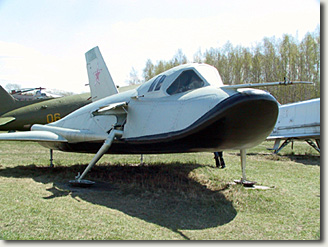
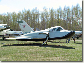
Today the '105.11' is an exhibit at the Air Force museum in Monino, Moscow
region.
 |
 |
The supersonic '105.12' never flew either, although it was ready for that,
unlike the '105.13' hypersonic version, of which only the fuselage was assembled
to undergo tests in thermal vacuum chamber. It withstood operating temperatures
of +1,300 degrees Centigrade during the ground tests, its heat resistance found
enough for over 50 flights.
Despite the Spiral programme was aborted, the effort was not in vain. The backup
created as well as the expertise gained sped up the development of the reusable
Buran spacecraft and made it much easier. Gleb Lozino-Lozinsky headed the work
on Buran's airframe, backed by the stock, the cooperation of 60 organisations,
and having the test methods and specialists at hand. A. Kucherenko, piloting the
Tu-95KM during the EPOS airdrop launch, was offered a job of test pilot of the
Myasishchev 3M-T (later - VM-T Atlant) carrier vehicle, developed to transport
elements of the Energiya-Buran system. Later, Igor Volk was the first to fly the
air-breathing prototype of Buran, and subsequently headed the team of test
pilots under the Buran programme, and even was sent to space in 1984, as part of
training for piloting the reusable spacecraft. Also, good use was made of the
EPOS scaled replicas - the BOR unmanned orbital aerospaceplanes that were
launched to space to test heat-resistant coating for Buran.
Vadim LUKASHEVICH
Drawings by Andrey YURGENSON and Vadim LUKASHEVICH
|
|
|
|
Переход на:


Web-master: ©Вадим Лукашевич 1998-2007
E-mail: buran@buran.ru